How to use the iPod Nano 6 LCD for LittlevGL
This blog tells you how to hack the screen that is supposed to display in an Apple’s iPodNano6 for LittlevGL with an Espressif ESP32 Wifi/BLE SoC.
All the source code can be downloaded at the bottom of the page.
Something about MIPI DSI
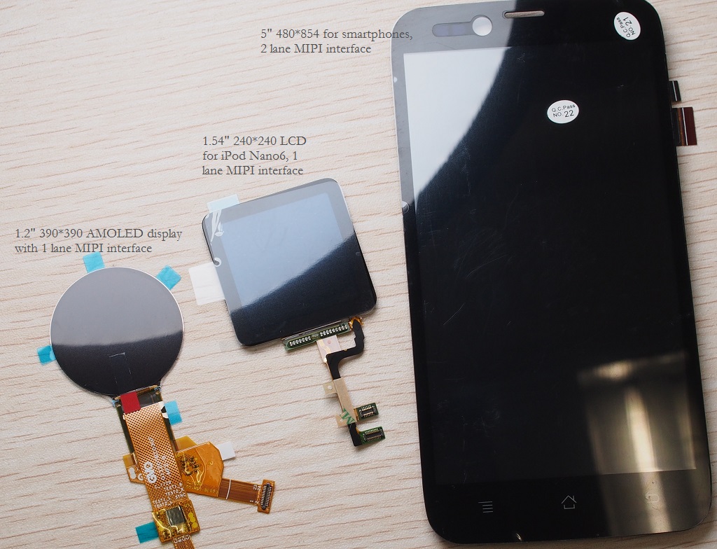
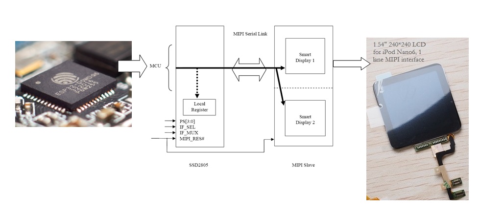
LCD for iPod Nano6 uses MIPI Display Serial Interface (MIPI DSI) which is a high-speed serial interface between a host processor and a display module. LCDs belong to this category are very common for smartphones, tablets, and smartwatches. Reference is available from MIPI alliance page. Some MIPI LCDs on hands are shown here.
Googling the keyword MIPI brings up several pdf documents of hundred pages. It is always fun to learn from specifications like this - http://bfiles.chinaaet.com/justlxy/blog/20171114/1000019445-6364627609238902374892404.pdf.
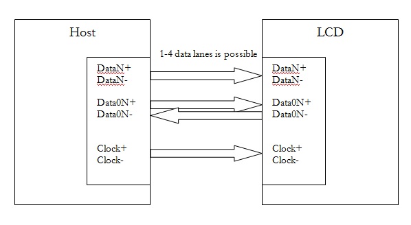
It states “MIPI DSI specifies the interface between a host processor and a display…” and finally a picture like this shows up that I can barely understand.
If a 100-pages specification takes too much time, this may be all you need to know about MIPI D’PHY RX
https://www.edn.com/Pdf/ViewPdf?contentItemId=4440302
Transmission speed of MIPI is very high, ranging from 1.0Gbps/lane to 4.5Gbps/lane with 1-4 data lane plus 1 clock signal all in differential buses. Voltage swing driven by the difference buses is also different from RGB/MCU-typed LCD. For MIPI DSI there are high-speed (HS) and low-speed (LS) modes to drive 200mV peak-to-peak and 1.2V whereas data of RGB/MCU-typed LCDs is carried with single-ended signals matching VDDIO of MCU host.
Table below summaries the difference.
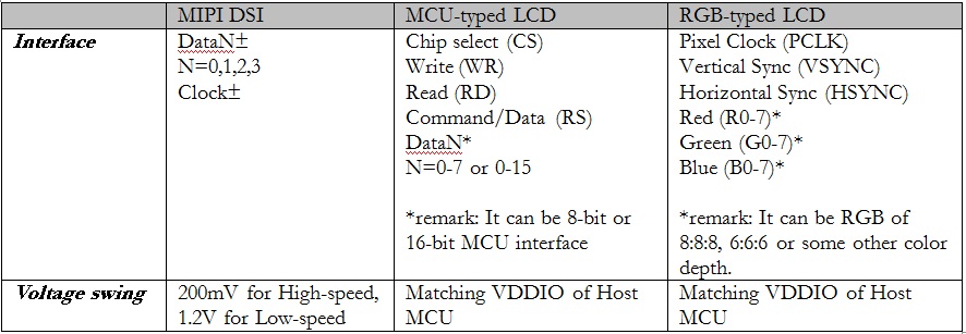
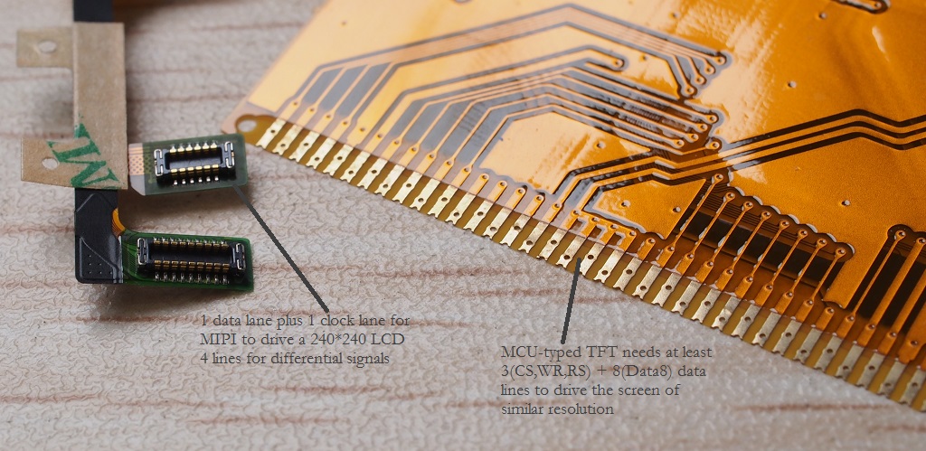
Usually interface of a MIPI LCD needs much less pins and lower voltage than its MCU/RGB counterpart.
MIPI bridge Chip
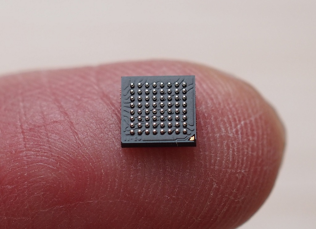
The problem is, how do we drive a MIPI display when there is no DSI output from our MCU (like ESP32) and how to port it to LittlevGL? Here comes the MIPI bridge IC - SSD2805, which is an interface chip to convert between RGB/8080 video signal to MIPI signal.
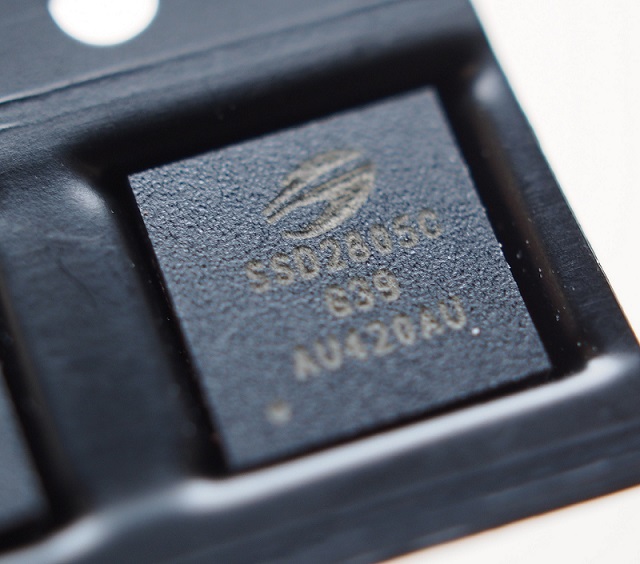 This is a very tiny chip of 5*5mm with 0.5mm pitch BGA!
Block diagram of my setup
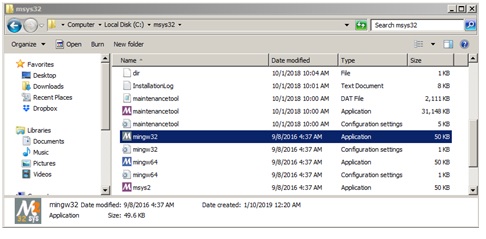
 ESP32 is programmed with ESP-IDF (Espressif IoT Development Framework). Its installation procedure is described in full details at Espressif’s documentation site. My host computer is a Windows 7 Pro SP1 64-bit Operating System. Hardware is an old Intel Core i5 with 8GB RAM. I have followed the default installation path described in ESP-IDF’s Getting Started Guide. It gave me back a mingw32.exe application under C:\msys32.
 At first I was not comfortable with command line tool like mingw32.exe. With innumerable Google searches I tried to install Eclipse IDE. Unfortunately all hours in Eclipse became futile. At the end I found the time spent on configuring Eclipse was even more than programming itself so I just gave it up. Don’t mean Eclipse is bad. It is just me not able to get it work.
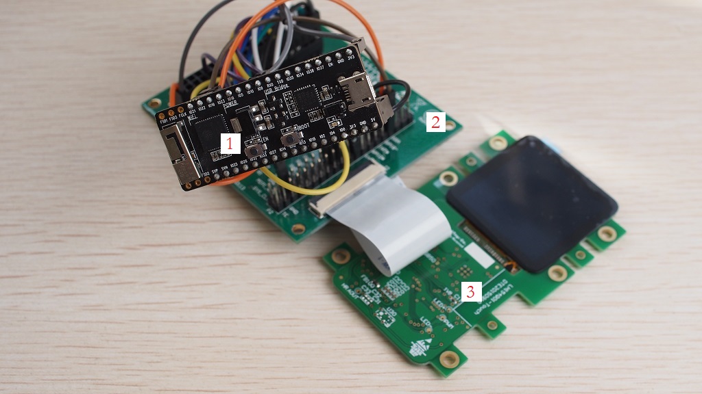
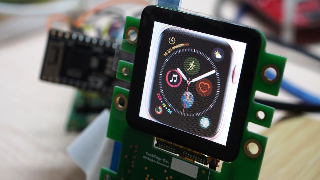
Because there is no standard evaluation kit for ESP32 + SSD2805 + MIPI Display combo, I was forced to use jumper cables to wire up things with mess like this :(
Hardware
Boards employed include:
- ESP32-Pico-Kit v4
- SSD2805 breakout board Release 3
- 1.54 inch LH154Q01 MIPI display with CTP on PCB. SSD2541 CTP driver is soldered on this board.
- Plus a lot jumper cables!
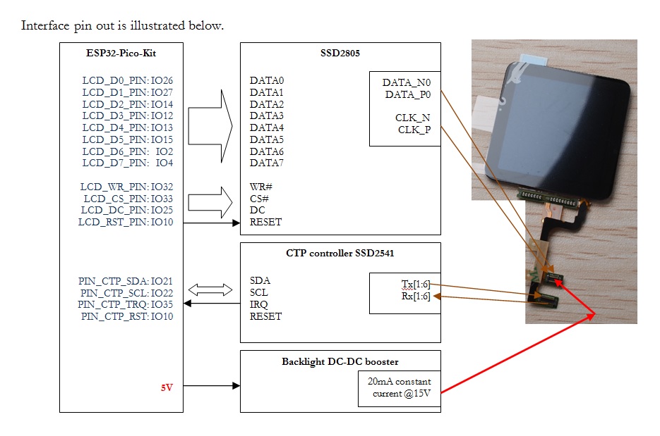
The pinout diagram is illustrated below.
Note
- On SSD2805 breakout board, VDDIO_CTRL pin driven low to conduct mosfet for VDDIO_CORE.
- EXT_5V should be supplied with 5V (from usb is OK). This is for backlight controller IC.
- PWM pin for backlight controller IC should be driven high (3.3V) to enable it.
- DIP switch setting on SSD2805 EVK is, from left to right: 01000011 (0=ON on dip switch).
- PCLK/RD# on SD2805 EVK board should be driven high, not floating. This pin is a pull-down pin by default. If there is no reading required, pull it up to drive RD# pin high forever.
Software
To work with LittlevGL, the prerequisite is a fully working LCD and touch screen drivers outside it. I started with a program of 5 source files to drive the LCD listed below:
1. i2s_8080_hello_world.c
2. SSD2805_8080_drv.c and .h
3. i2s_lcd.c and .h
Source files i2s_lcd.c and .h were modified from their GitHub source.
ESP32 uses I2S module to write in 8080 8-bit parallel mode. DMA is used to queue command and data.
Full source code of this project i2s_8080_lcdcan be downloaded at the end of this page.
To compile this project, just copy the complete folder to any place you find it convenient, in my case it is D:\esp32\i2s_8080_lcd.
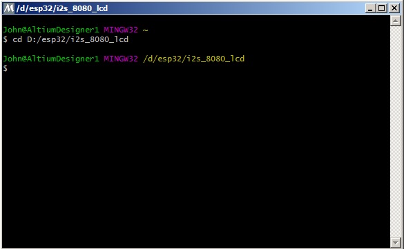
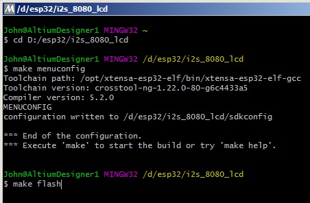
Launch mingw32.exe from C:/msys32

Change directory to the root of Makefile with cd D:/esp32/i2s_8080_lcd
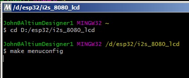
Set the right serial port with make menuconfig
Browse to Serial flasher config —> set it to COM2 (for my case).
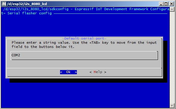
Click EXIT several times and click <Yes> at the end to save new configurations.
The last step is to make flash
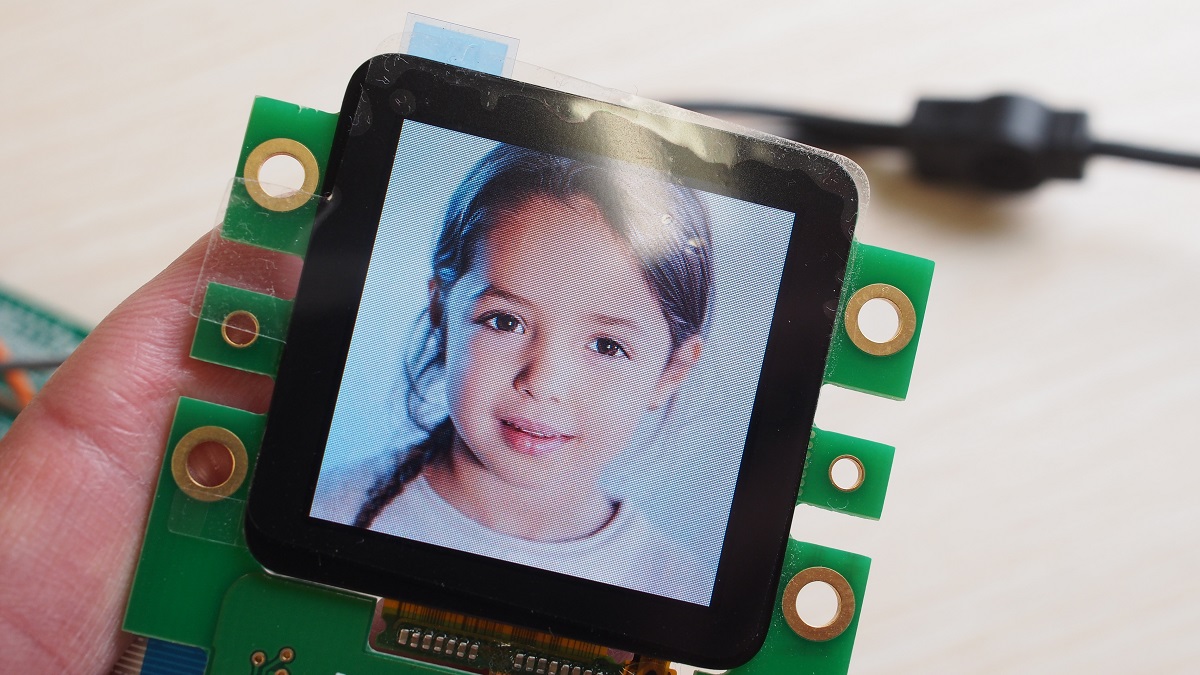
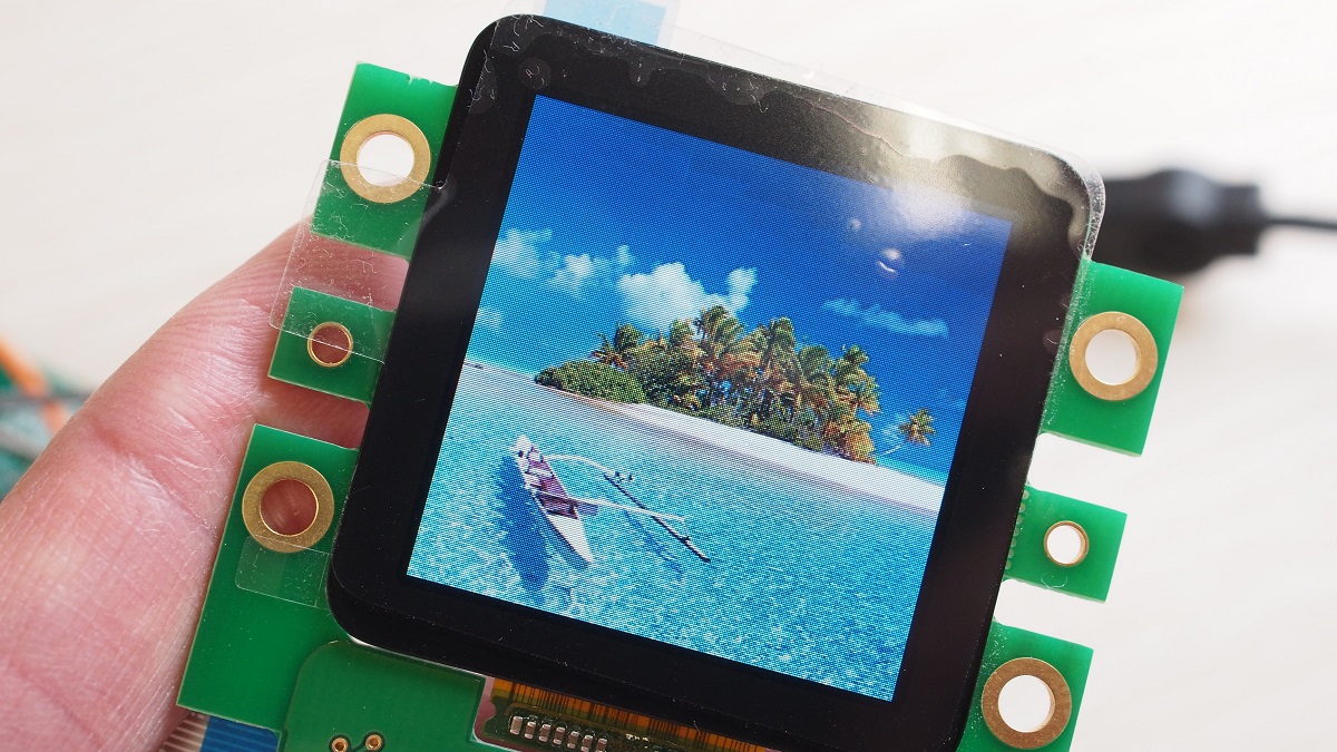
Now a fake AppleWatch is visible.
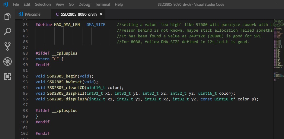
Screen capture below shows all public functions of SSD2805. No text print, no shape draw or framebuffer operation. All GUI-related features are left to LittlevGL with a single API function SSD2805_dispFlush(args), which has been designed to match the blueprint required not more or less. This is also the only function get called when screen refresh or update is required.
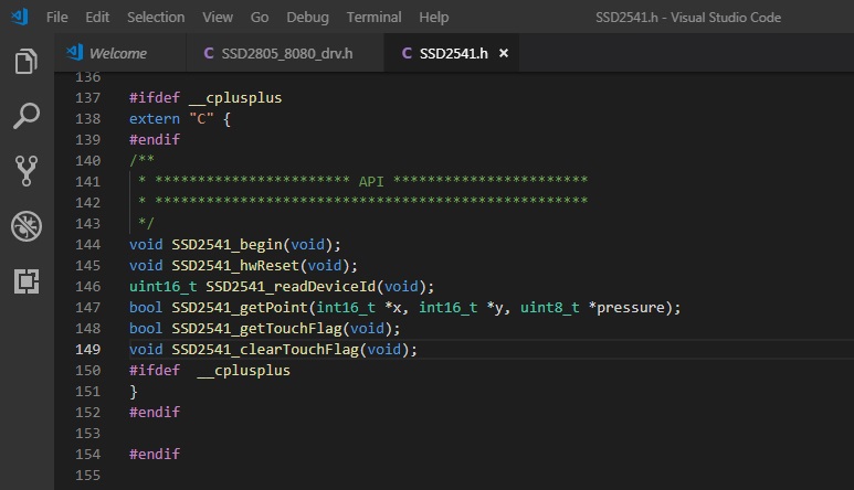
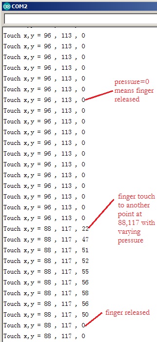
Similarly the driver for CTP was developed and tested with basic program that prints coordinates of finger with pressure to serial port. Screen capture of SSD2541.h is shown below. API function SSD2541_getPoint(args) is the only interface required by LittlevGL.
In mingw32 console type cd D:/esp32/SSd2541_drv_test, repeat the same procedure as SSD2805 by make menuconfig, set Serial flasher config —> to COM2 (in my case). Save changes and finally make flash. This time we need a terminal program like Serial Monitor of Arduino. Screen capture below shows a stream from Serial Monitor with finger released from (96,113), touched at (88,117) with varying pressure and then released again. LittlevGL requires that touch coordinates shoud be the last valid point when the figner is released.
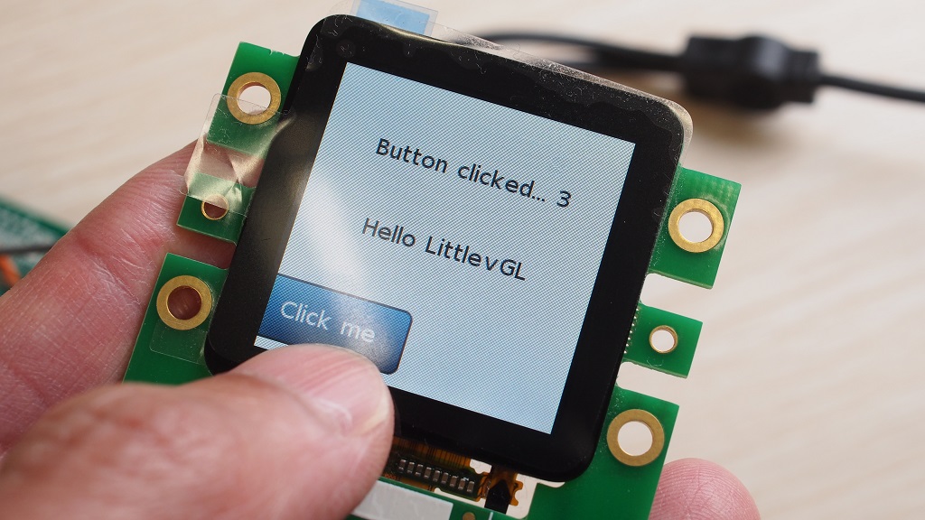
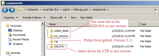
Everthing seems ready for porting LittlevGL. The last program littlevgl_port is the final example of this blog to demonstrate several LittlevGL features (not all) including label, button, and image display. Browse to the components folder you will see exactly the same driver for SSD2805 and SSD2541. lvgl (version 5.3 commit 17c19fc) has been pulled directly from github.
There are few somethings to do before LittlevGL can be used:
- modify
lv_conf.hfrom its template for our screen resolution. This header is located in the same root as Makefile, the project directory./* Horizontal and vertical resolution of the library.*/ #define LV_HOR_RES (240) #define LV_VER_RES (240) #define LV_DPI 100 - In the main file
littlevgl_example.c, define a local function to callSSD2805_dispFlush(args)and then inform LittlevGL that screen flush is ready withlv_flush_ready()./** * @brief API for LittlevGL with LV_VDB_SIZE!=0 in lv_conf.h */ static void ex_disp_flush(int32_t x1, int32_t y1, int32_t x2, int32_t y2, const lv_color_t * color_p) { SSD2805_dispFlush(x1, y1, x2, y2, (const uint16_t*)color_p); lv_flush_ready(); } - In the main file
littlevgl_example.c, define a local function to callSSD2541_getPoint(args)to store the last valid finger position to data->point.x and point.y. Pressure is not required for LittelvGL so a NULL is passed./** * @brief API for touch screen */ static bool ex_tp_read(lv_indev_data_t * data) { int16_t ctp_x, ctp_y; bool sta = SSD2541_getPoint(&ctp_x, &ctp_y, NULL); (sta==true)? (data->state = LV_INDEV_STATE_PR):(data->state = LV_INDEV_STATE_REL); data->point.x = ctp_x; data->point.y = ctp_y; return false; } - Define a tick function as heart-beat for LittlevGL and register this function for ESP32.
/** * @brief Heart beat for LittlevGL */ static void lv_tick_task(void) { lv_tick_inc(portTICK_RATE_MS); } //... esp_register_freertos_tick_hook(lv_tick_task); //this is specific to ESP32 - The last step is to initialize SSD2805, SSD2541, lv_init(), and register the API functions.
 SSD2805_begin();
 SSD2541_begin();
 lv_init();

 lv_disp_drv_t disp_drv;
 lv_disp_drv_init(&disp_drv);
 disp_drv.disp_flush = ex_disp_flush;
 lv_disp_drv_register(&disp_drv);

 lv_indev_drv_t indev_drv;                       /*Descriptor of an input device driver*/
 lv_indev_drv_init(&indev_drv);                  /*Basic initialization*/
 indev_drv.type = LV_INDEV_TYPE_POINTER;         /*The touchpad is pointer type device*/
 indev_drv.read = ex_tp_read;                    /*Library ready your touchpad via this function*/
 lv_indev_drv_register(&indev_drv);              /*Finally register the driver*/
The result is a fully operational CTP with button, image display, and text printing!